I/F ボードとしてCH341TまたはFT232Hを利用する。
Raspberry piやESPシリーズなどの組み込みシステムの制御に適したマイコンには、GPIO,I2CやSPIなどのポートが備わってるのが特徴の一つです。これらのI/Fを通じて様々なセンサー(例えば温度、湿度、気圧など)や小型表示器、PWM制御器などに接続できます。
一方、WindowsPCなどに広く使われているx86には、残念ながらセンサーなどのハードウェアを直接制御可能なポートがありません。 PCにはUSBポートがありますが、このUSBポートからシリアルやI2Cへ変換するハードウェアを探してみたらCH341Tがamazonなどで安価に販売されていました。
そこで、USBからCH341TとFT232H経由で、次のような機能を試してみました。
(1)AHT20で温度、湿度のデータを取得
(2)OLEDディスプレイSSD1306へ文字表示
(3)PCA9685でサーボモータを駆動
https://github.com/crescentvenus/USBtoI2C
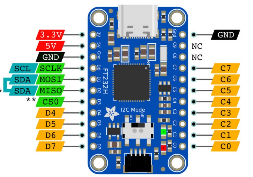
Power Pins
5V – this is the 5V power from the USB input.
GND – this is the common ground for all power and logic.
3V power output – The new version has a 3.3V power output pin for up to 500mA
GPIO Pins
D4 to D7 – can be used as either digital inputs or outputs.
C0 to C7 – can be used as either digital inputs or outputs.
I2C Pins
SCL – the I2C clock signal is on D0.
SDA – the I2C data is on D1+D2.
I2C switch – The new version has a switch that connects D1 and D2 for easy I2C interfacing. Move the switch to ON to use I2C and/or the STEMMA QT connector. You can then use either D1 or D2 for SDA.
On the original version only: Note that there are two pins (D1 and D2) which must be tied together and treated as one to use I2C.
SPI Pins
SCLK – the SPI clock signal is on D0.
MOSI – Microcontroller Out, Serial In is on D1.
MISO – Microcontroller In, Serial Out is on D2.
CS0 – Chip Select is on D3. This is not used by Blinka, instead use one of the GPIO pins from above (see example section).
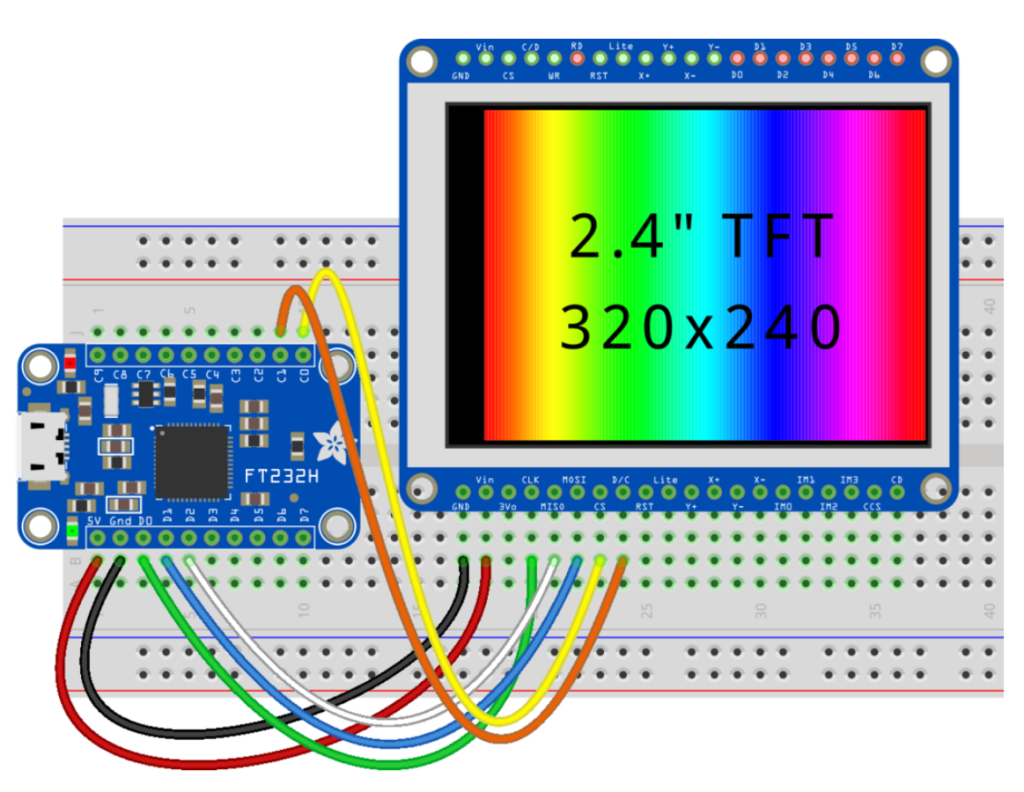
ST7789ピン FT232Hピン 説明
VCC 3.3V 電源(3.3V推奨、5Vは不可の場合あり)
GND GND グランド
SCL D0 (SCLK)
SPIクロック信号 SDA D1 (MOSI) SPIデータ入力(Master Out Slave In)
RES D5 リセットピン
DC D6 データ/コマンド選択ピン
BLK 3.3VまたはD7 バックライト(オプション、3.3VまたはGPIOで制御)
CircuitPython Libraries on any Computer with FT232H
https://learn.adafruit.com/circuitpython-on-any-computer-with-ft232h/windows
GPIOサンプル
OUTPUT サンプル
import time
import board
import digitalio
led = digitalio.DigitalInOut(board.C0)
led.direction = digitalio.Direction.OUTPUT
while True:
led.value = True
time.sleep(0.5)
led.value = False
time.sleep(0.5)
INPUT サンプル
import board
import digitalio
led = digitalio.DigitalInOut(board.C0)
led.direction = digitalio.Direction.OUTPUT
button = digitalio.DigitalInOut(board.C1)
button.direction = digitalio.Direction.INPUT
while True:
led.value = button.value
I2Cサンプル
# SPDX-FileCopyrightText: 2021 ladyada for Adafruit Industries
# SPDX-License-Identifier: MIT
import time
import board
from adafruit_bme280 import basic as adafruit_bme280
# Create sensor object, using the board’s default I2C bus.
i2c = board.I2C() # uses board.SCL and board.SDA
# i2c = board.STEMMA_I2C() # For using the built-in STEMMA QT connector on a microcontroller
bme280 = adafruit_bme280.Adafruit_BME280_I2C(i2c)
# OR create sensor object, using the board’s default SPI bus.
# import digitalio
# spi = board.SPI()
# bme_cs = digitalio.DigitalInOut(board.D10)
# bme280 = adafruit_bme280.Adafruit_BME280_SPI(spi, bme_cs)
# change this to match the location’s pressure (hPa) at sea level
bme280.sea_level_pressure = 1013.25
while True:
print(“\nTemperature: %0.1f C” % bme280.temperature)
print(“Humidity: %0.1f %%” % bme280.relative_humidity)
print(“Pressure: %0.1f hPa” % bme280.pressure)
print(“Altitude = %0.2f meters” % bme280.altitude)
time.sleep(2)
SPIサンプル
import board
import digitalio
import adafruit_rgb_display.ili9341 as ili9341
from PIL import Image
# Setup display
cs_pin = digitalio.DigitalInOut(board.C0)
dc_pin = digitalio.DigitalInOut(board.C1)
disp = ili9341.ILI9341(board.SPI(), cs=cs_pin, dc=dc_pin, baudrate=64000000)
# Load image and convert to RGB
image = Image.open(‘blinka.bmp’).convert(‘RGB’)
# Display it (rotated by 90 deg)
disp.image(image, 90)